You use this program to calculate the cumulative and manufacturing lead times of an item and to update the relevant fields against the stock item.
| Field | Description | ||||
|---|---|---|---|---|---|
| Start Processing | Select this to commence processing.
The manufacturing lead time (MLT) for a subcontract operation is calculated as: MLT = LT + (DTS + OFF) * NWR) where LT = lead time against the subcontract operation (i.e. the purchasing lead time). Note that this lead time is in absolute days and the non-working days ratio is therefore not applied to it. DTS = the dock to stock against the subcontract operation OFF = the offsite time against the subcontract operation MOVE = movement time (only include if not negative) NWR = non-working days ratio (calculated as: DAYS IN YEAR / (DAYS IN YEAR - NON-WORKING DAYS) as per your calendar (Company Calendar). When processing co-products, if the co-product type is defined as concurrent (BOM Co-products), then all co-products inherit the same lead times (i.e. lead and manufacturing lead times). For all co-products that are not Sequential, their lead time and the MLT (Manufacturing Lead Time) are set to the same as those for the notional part itself (including the dock to stock of the notional part, as it is assumed that the notional part's dock to stock is the same as its co-products' dock to stock). If the co-product type is sequential, then the manufacturing lead time is calculated for the co-product up until the time it is completed. In addition, for sequential co-products, the overall lead time (lead time including purchasing and subcontract) is only calculated for materials attached to the co-product up to the time the item is completed. For sequential co-products, the MLT (Manufacturing Lead Time) for all subsequent operations is subtracted from the Notional part's MLT/Lead time to obtain the co-products' lead time. If a co-product is attached multiple times to different operations, then the lowest operation's lead time and MLT is used. |
||||
| Select this to print the information currently displayed in the Report pane. | |||||
| Save Form Values | This option is only enabled in Design mode (see Automation Design). Your selections are saved and applied when the program is run in automated mode. | ||||
| Field | Description |
|---|---|
| Lead time calculation | |
| Re-calculate dynamic elapsed times |
Select this if you want the program to re-calculate dynamic elapsed times for operations that are defined as dynamic. If you do not select this option then the program uses the current dynamic elapsed times to calculate the lead time and manufacturing lead time. |
| After processing completed | These options are displayed within programs that can be automated. They enable you to indicate the action you want to perform once processing is complete (see Automation Design). |
The information in this pane is displayed once the calculation is complete, providing you did not select the option: After processing completed > Close this application.
This displays the log report resulting from the calculation.
The report includes the following information:
- whether the calculation was successfully completed
- whether structures exists with more than 15 levels
- whether a looping structure exists (parent parts are repeated as components in the same structure)
- the start and end times of processing
![[Note]](images/note.png)
|
|
|
You use the After processing completed options to print or email this information. |
|
The lead time calculation program performs the following routine:
-
Clearing of the current lead times:
The manufacturing lead time field is cleared. The total lead time field is cleared if either components or operations are attached to the item.
-
Calculation of the longest lead times:
The program scans the structure file - lowest level first - accumulating the lead times for each level and carrying the longest lead times through to the next level until the highest level is reached.
Raw materials (i.e. bought-out items) are deemed to have a manually entered lead time which is the time from the date that the purchase order is placed until the material arrives.
Sub-assemblies have a lead time which is the time of the longest components' lead time plus the total operation time (elapsed time + move + queue).
The longest lead time will take into account the fact that a particular component may be required some time into the manufacturing process. This could be defined as a number of offset days or a particular operation number.
![[Note]](images/note.png)
If a component is offset by an operation that does not exist, then the program assumes that the component is required at the beginning of the manufacturing process.
-
The Lead time (days) field against the parent item (Stock Code Maintenance) is updated with the manufacturing lead time calculated.
-
You should run the BOM Structure Validation program before using the Lead Time Calculation program. The reason is that the calculation aborts if any errors are encountered (e.g. structures with more than 15 levels and parent parts that are repeated as components in the same structure).
-
Ensure that working and non-working days in your company calendar are correctly defined (Company Calendar), because the lead time varies according to the number of non-working days defined.
Electronic Signatures provide security access, transaction logging and event triggering. This enables you to increase control over your system changes.
Access to the following eSignature transactions within this program can be restricted at Operator, Group, Role or Company level. You configure this using the Electronic Signatures program.
| eSignature Transaction | Description |
|---|---|
| BOM Lead time calculation |
Controls access to the Start Processing function in the Lead Time Calculation program. |
-
Amendment journals are created if these are required for Inventory (Inventory Setup - General).
Inserting Application Help
You would typically follow this procedure to display help for the current program in a customized pane that can be pinned to the program window.
Information includes step-by-step instructions for the various functions available within the program, including a brief overview of what the program does, what setup options are required and how to personalize the program.
-
Open the program for which you want to insert application help into a customized pane.
This functionality is only available for a program that has panes.
-
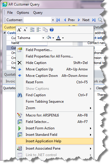
Right-click any form field.
You can also click the triangle menu icon that appears in the title area of a pane.
-
Select Insert Application Help from the context-sensitive menu.
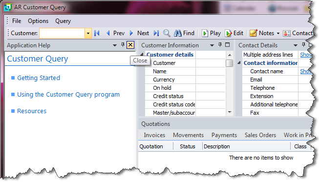
The application help appears in a pane within your program. You can reposition the pane using the docking stickers or pin it to the program window.
Removing the Application Help pane
If you no longer want to display application help in a pane for your current program, you can simply remove it.
-
Select the Close icon in the right-hand corner of the application help pane.
-
Confirm that you want to delete the pane.

